The new CT technology will be integrated into the NDT conventional digital detection system, including online detection and in-service detection, surpassing the constraints of existing offline detection and precision fixtures, and able to adapt to various detection targets (size, shape, conventional to micro focus) and on-site working conditions. Specific application scenarios include online detection of materials, pipelines, containers, workpieces, and on-site in-service detection of mobile detection equipment
1.Traditional CT (vertical axis isocenter): Full scan, Half scan, Finite angle
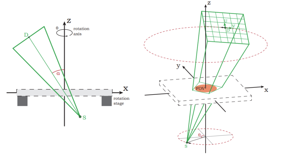
2.Non traditional CT: Limited angle, limited frame high-speed CT, Rotational tomography CT
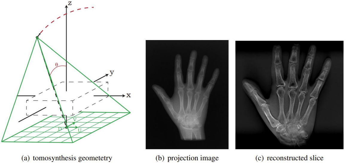
3.Fault synthesis CT
4.Channel CT
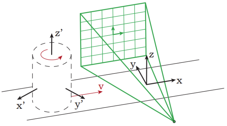
The geometric shape of an object moving on a conveyor belt with a fixed source and a flat detector.
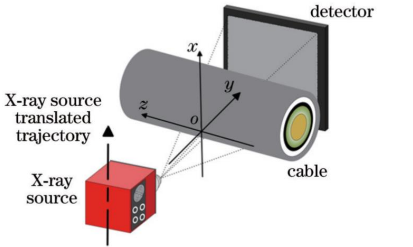
5. Source translation scanning CT
A local CT imaging method for detecting the bottom of the water blocking buffer layer of in-service high-voltage cables. The scanning method is as follows: the tested cable and flat panel detector remain stationary, the X-ray source moves in an equidistant straight line parallel to the detector direction and collects projection data, and the detection object is placed close to the detector. Due to the limitations of the movement distance of the radiation source and the size of the detector, it is not possible to collect complete projection data for image reconstruction. In order to ensure the maximum projection angle coverage range, this paper places the center of the imaging area at the intersection of the line formed by the detector at the upper end of the source trajectory and the line formed by the detector at the lower end of the source trajectory.
6.Adaptive Scaling CT
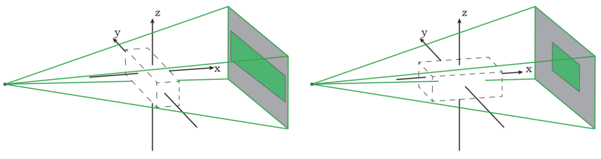
For slender objects, the fixed distance between the light source and the detector can result in poor performance of the detector array in certain viewing directions.
7. Automatic projection alignment CT
Another advantage of considering projection geometry in vector form is its inherent flexibility in correcting projection misalignment. This misalignment may take various forms. For example, the center of rotation may not be fully projected onto
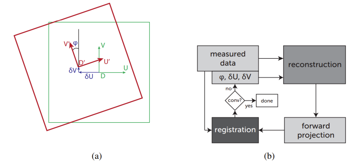
(a)A moving and tilted detector array viewed from the perspective of the X-ray source.
(b) Schematic diagram of the iterative program for automatically estimating detector offset and tilt.
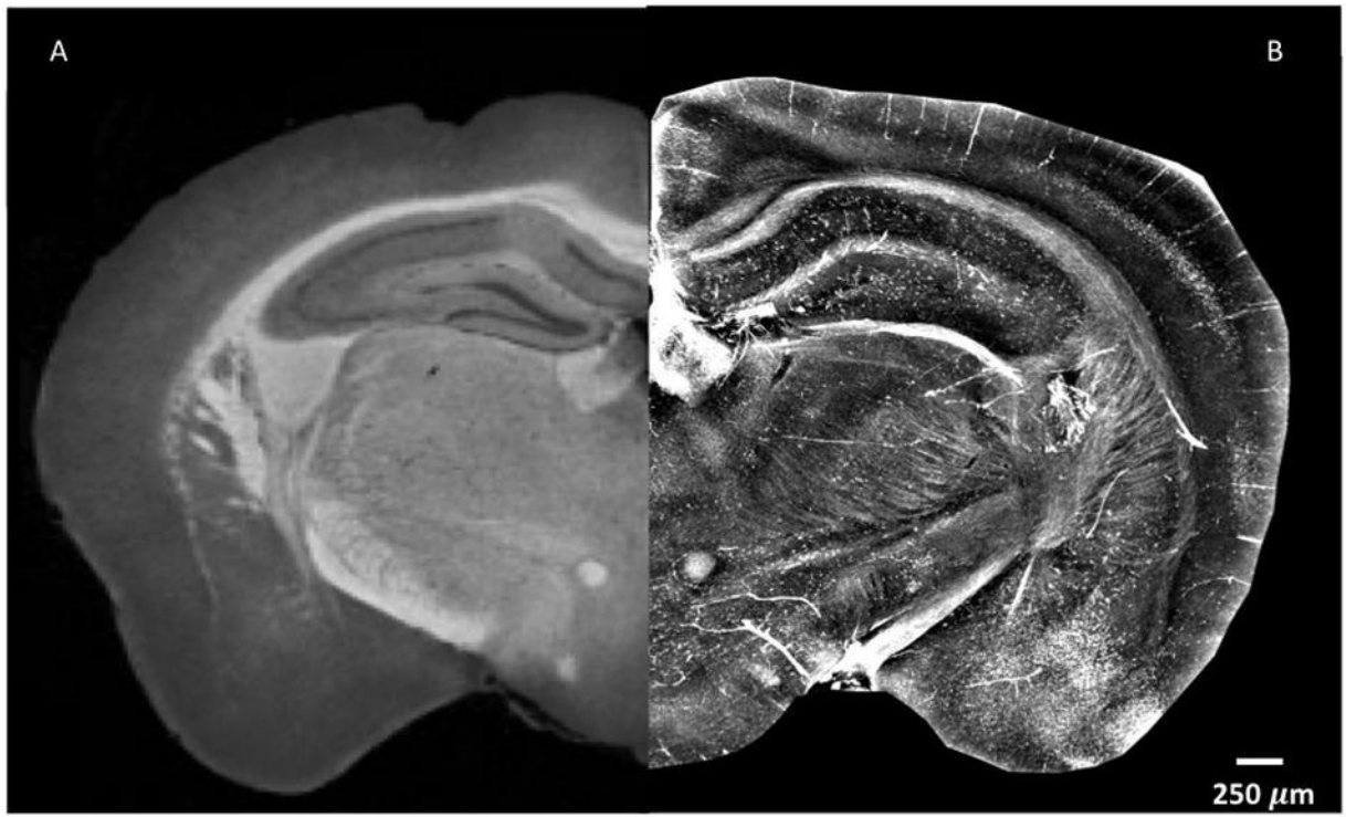
8. Contrast enhanced CT
It has high accuracy and sensitivity in detecting porosity and crack defects in metal materials. Overall, X-ray phase contrast imaging has high accuracy and sensitivity in detecting porosity and crack defects in metal materials, and is a promising new non-destructive testing technology.
The X-ray phase contrast imaging technology has a wide range of application scenarios in detecting porosity and crack defects in metal materials
⚫ Pore detection
⚫ Detect porosity defects in cast and forged metal parts in the aerospace industry, such as aircraft engine blades, compressor blades, etc.
⚫ Detect porosity defects in aluminum castings used in the automotive industry, such as engine cylinder blocks and body structural components.
⚫ Detect porosity defects in metal structures such as oil pipelines and storage tanks.
⚫ Crack detection
⚫ Detect fatigue cracks in metal components in the aerospace industry, such as aircraft fuselage, engine blades, etc.
⚫ Detect crack defects in railway components such as rails and wheels.
⚫ Detect crack defects in nuclear power plant pipelines and pressure vessels.
⚫ Detect welding defects such as cracks and lack of fusion in the weld area.
Phase contrast imaging technology can clearly display small pores and cracks, obtain the morphology and location information of defects, and play an important role in non-destructive testing in the above-mentioned fields